for (uint32_t p = 0; p < hxw; ++p)
         {
             int i = p % scene.height;
             int j = p / scene.height;
             // generate primary ray direction
             float x = (2 * (i + 0.5) / (float)scene.width - 1) *
                       imageAspectRatio * scale;
             float y = (1 - 2 * (j + 0.5) / (float)scene.height) * scale;

             Vector3f dir = normalize(Vector3f(-x, y, 1));
             for (int k = 0; k < spp; k++)
             {
                 framebuffer[p] += scene.castRay(Ray(eye_pos, dir), 0) / spp;
             }
             pocess++;
                 UpdateProgress(pocess / (float)(scene.height * scene.width));
         }
然后加入这几个头文件:
1
2
3
4
5
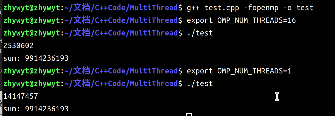
#include<thread> #include<pthread.h> #include<omp.h> //linux library for getting cpu num #include"unistd.h"
#pragma omp parallel for shared(pocess)
    for (uint32_t p = 0; p < hxw; ++p)
    {
        int i = p % scene.height;
        int j = p / scene.height;
        // generate primary ray direction
        float x = (2 * (i + 0.5) / (float)scene.width - 1) *
                  imageAspectRatio * scale;
        float y = (1 - 2 * (j + 0.5) / (float)scene.height) * scale;

        Vector3f dir = normalize(Vector3f(-x, y, 1));
        for (int k = 0; k < spp; k++)
        {
            framebuffer[p] += scene.castRay(Ray(eye_pos, dir), 0) / spp;
        }
        pocess++;
            UpdateProgress(pocess / (float)(scene.height * scene.width));
    }
if (dotProduct(ray.direction, normal) > 0) return inter; double u, v, t_tmp = 0; Vector3f pvec = crossProduct(ray.direction, e2); double det = dotProduct(e1, pvec); if (fabs(det) < EPSILON) return inter;
double det_inv = 1. / det; Vector3f tvec = ray.origin - v0; u = dotProduct(tvec, pvec) * det_inv; if (u < 0 || u > 1) return inter; Vector3f qvec = crossProduct(tvec, e1); v = dotProduct(ray.direction, qvec) * det_inv; if (v < 0 || u + v > 1) return inter; t_tmp = dotProduct(e2, qvec) * det_inv;
// TODO find ray triangle intersection if(t_tmp<0) return inter; inter.distance=t_tmp; inter.happened=true; inter.normal= this->normal; inter.coords=ray(t_tmp); inter.obj=this; inter.m=this->m; return inter; } //Bounds3.hpp inlineboolBounds3::IntersectP(const Ray &ray, const Vector3f &invDir, conststd::array<int, 3> &dirIsNeg)const { // invDir: ray direction(x,y,z), invDir=(1.0/x,1.0/y,1.0/z), use this because Multiply is faster that Division // dirIsNeg: ray direction(x,y,z), dirIsNeg=[int(x>0),int(y>0),int(z>0)], use this to simplify your logic // TODO test if ray bound intersects Vector3f t_minTemp = (pMin - ray.origin) * invDir; Vector3f t_maxTemp = (pMax - ray.origin) * invDir; Vector3f t_min = Vector3f::Min(t_minTemp, t_maxTemp); Vector3f t_max = Vector3f::Max(t_minTemp, t_maxTemp);
#include<iostream> #include<chrono> #include"omp.h" using std::cout; using std::endl; intmain() { longlong sum = 0; auto start = std::chrono::system_clock::now(); #pragma omp parallel reduction(+:sum) #pragma omp for for (int i = 3; i < 500000; i++) { bool flag = true; for (int j = 2; j < i; j++) { if (i % j == 0) { flag = false; break; } } if (flag) sum += i; } auto end = std::chrono::system_clock::now(); cout<<std::chrono::duration_cast<std::chrono::microseconds>(end-start).count()<<endl; cout << "sum: " << sum << endl; cout.flush(); }
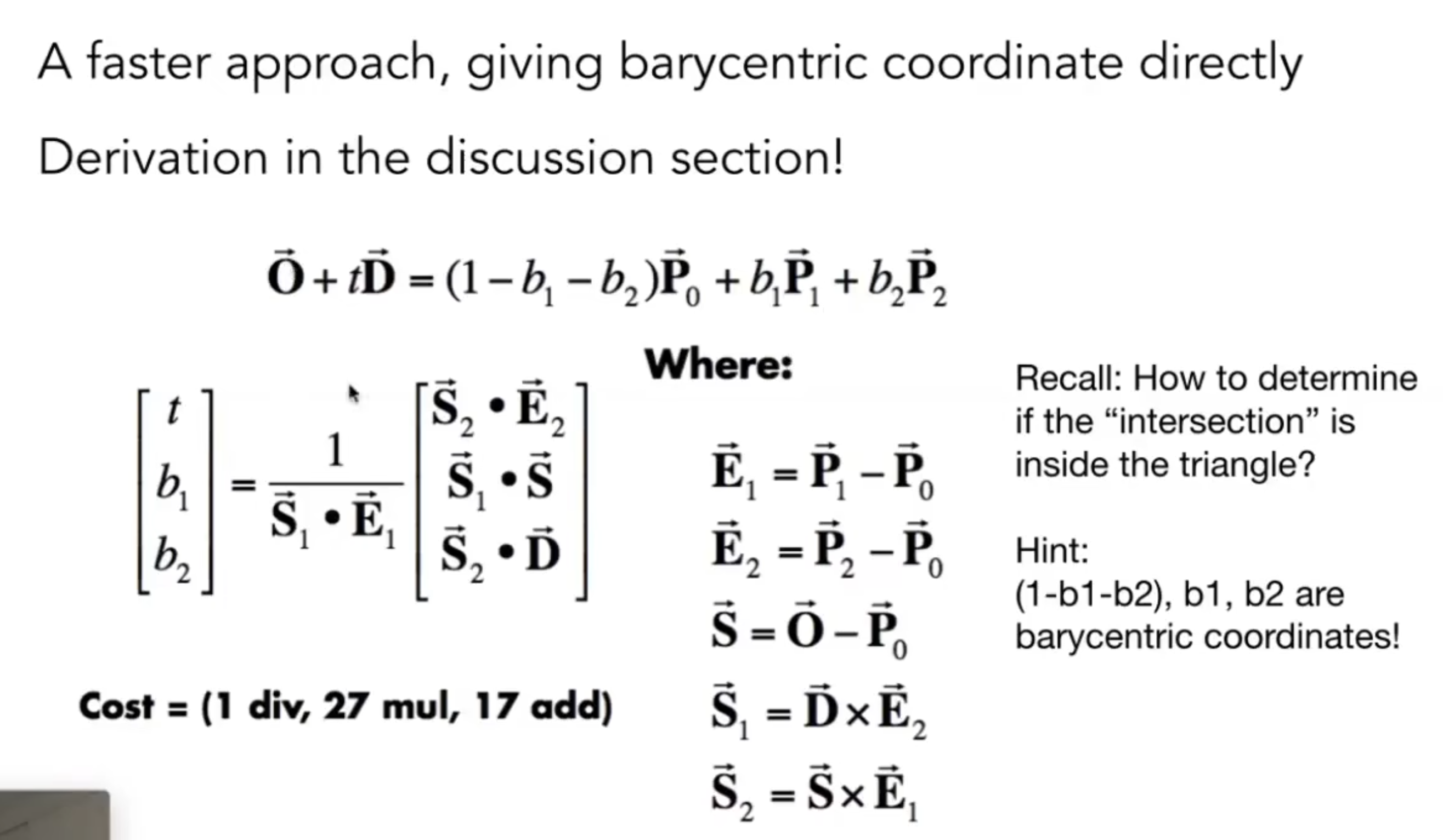
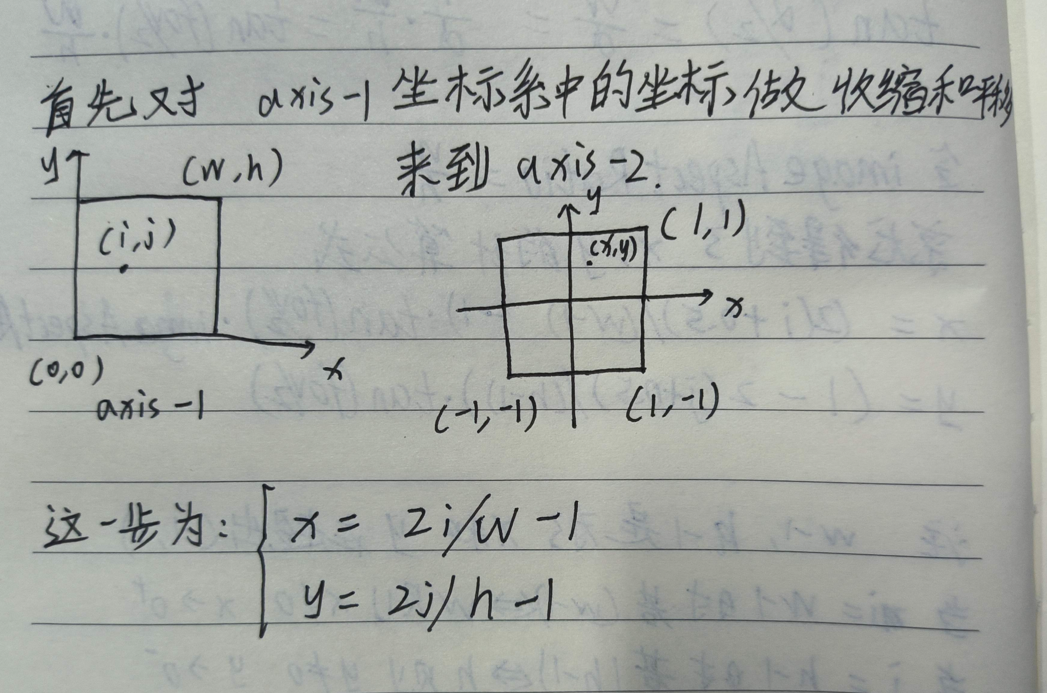
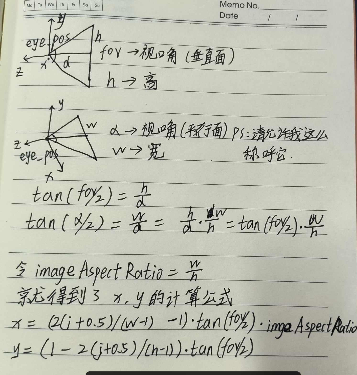
//Render for (uint32_t j = 0; j < scene.height; ++j) { for (uint32_t i = 0; i < scene.width; ++i) { // generate primary ray direction float x = (2 * (i + 0.5) / (float)scene.width - 1) * imageAspectRatio * scale; float y = (1 - 2 * (j + 0.5) / (float)scene.height) * scale; // TODO: Find the x and y positions of the current pixel to get the // direction // vector that passes through it. // Also, don't forget to multiply both of them with the variable // *scale*, and x (horizontal) variable with the *imageAspectRatio* Vector3f dir = normalize(Vector3f(x, y, -1)); framebuffer[m++]=scene.castRay(Ray(eye_pos,dir), 0); } UpdateProgress(j / (float)scene.height); }
Intersection BVHAccel::getIntersection(BVHBuildNode* node, const Ray& ray)const { // TODO Traverse the BVH to find intersection // invDir: ray direction(x,y,z), invDir=(1.0/x,1.0/y,1.0/z), use this because Multiply is faster that Division // dirIsNeg: ray direction(x,y,z), dirIsNeg=[int(x>0),int(y>0),int(z>0)], use this to simplify your logic Intersection intersect; Vector3f invdir(1./ray.direction.x,1./ray.direction.y,1./ray.direction.z); std::array<int, 3> dirIsNeg; dirIsNeg[0] = ray.direction.x>0; dirIsNeg[1] = ray.direction.y>0; dirIsNeg[2] = ray.direction.z>0; if(!node || !node->bounds.IntersectP(ray,ray.direction_inv,dirIsNeg)) { return intersect; }
boolrayTriangleIntersect(const Vector3f& v0, const Vector3f& v1, const Vector3f& v2, const Vector3f& orig, const Vector3f& dir, float& tnear, float& u, float& v) { // TODO: Implement this function that tests whether the triangle // that's specified bt v0, v1 and v2 intersects with the ray (whose // origin is *orig* and direction is *dir*) // Also don't forget to update tnear, u and v. auto e1 = v1 - v0, e2 = v2 - v0, s = orig - v0; auto s1 = crossProduct(dir, e2), s2 = crossProduct(s, e1);
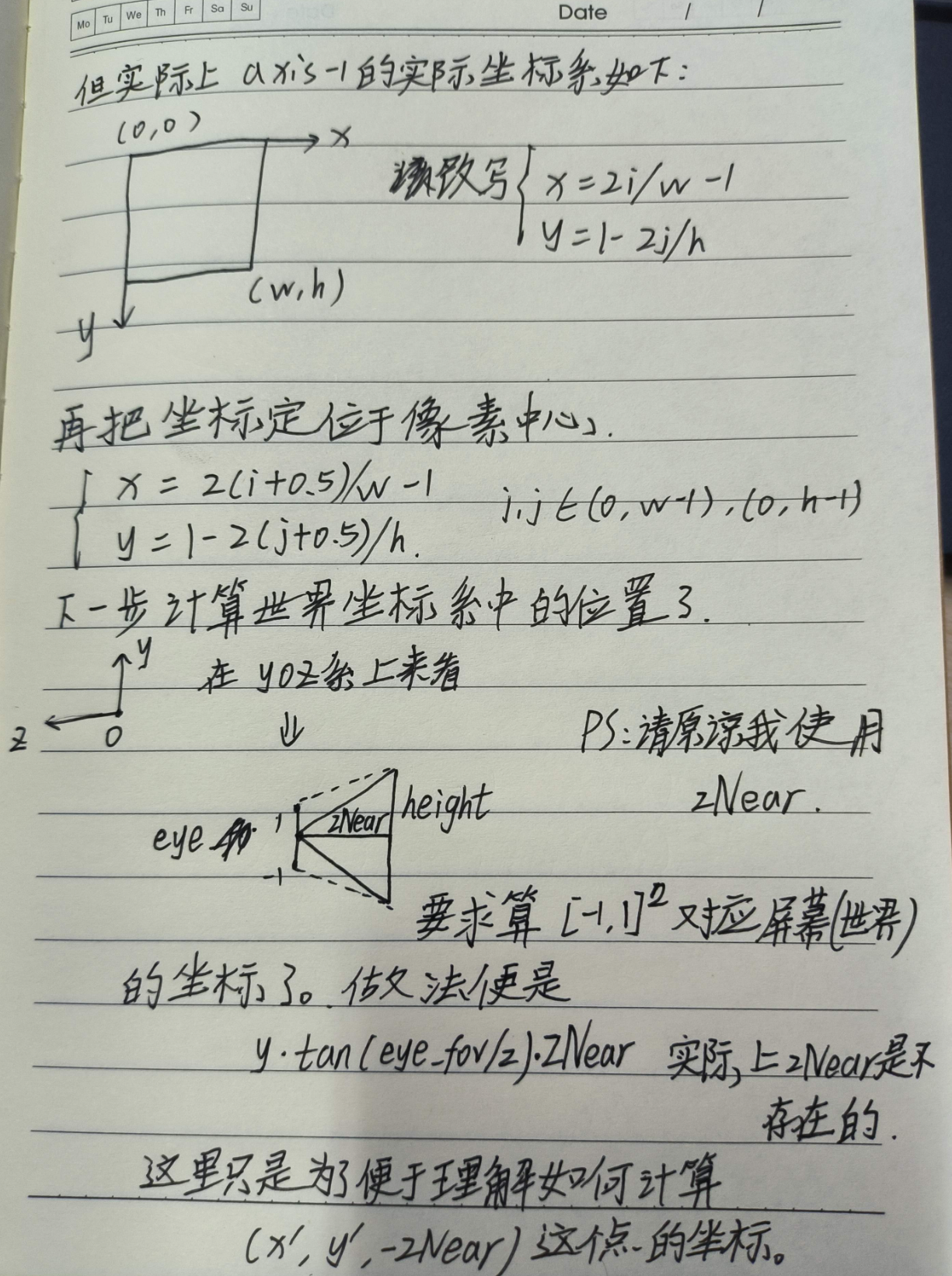
//Render for (int j = 0; j < scene.height; ++j) { for (int i = 0; i < scene.width; ++i) { // generate primary ray direction float x; float y; // TODO: Find the x and y positions of the current pixel to get the direction // vector that passes through it. // Also, don't forget to multiply both of them with the variable *scale*, and // x (horizontal) variable with the *imageAspectRatio* x=(((i+0.5f)/static_cast<float>(scene.width-1)*2.0f)-1.0f)*scale*imageAspectRatio; y=(1.0f-(j+0.5f)/static_cast<float>(scene.height-1)*2.0f)*scale; //其实就是把"zNear"设置为了 1 Vector3f dir = normalize(Vector3f(x, y, -1)); // Don't forget to normalize this direction! framebuffer[m++] = castRay(eye_pos, dir, scene, 0); } UpdateProgress(j / (float)scene.height); }
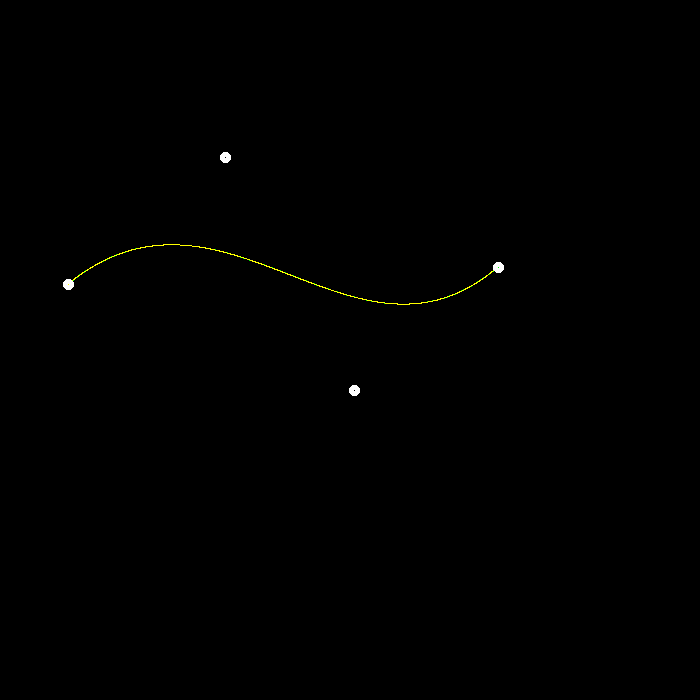
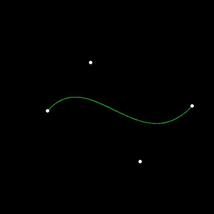
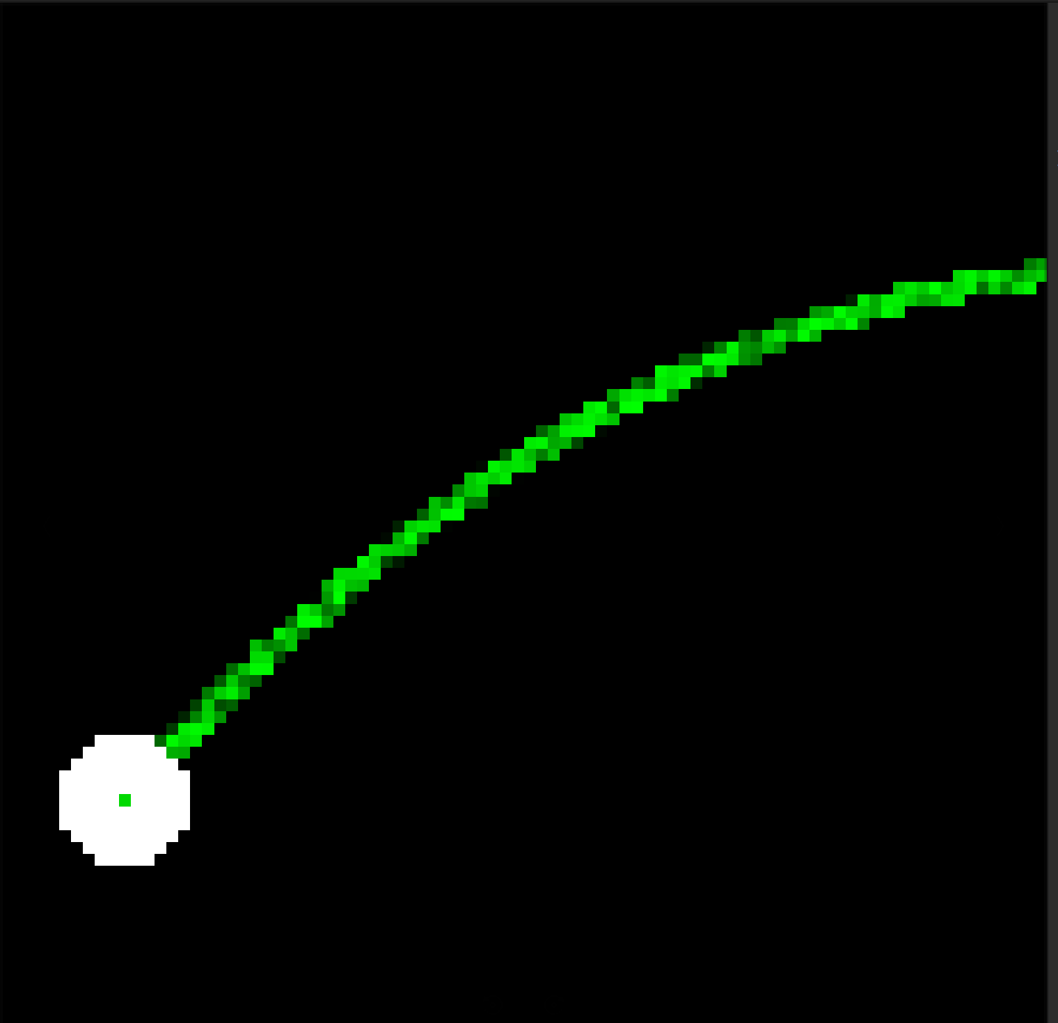
voidbezier(conststd::vector<cv::Point2f> &control_points, cv::Mat &window){ // TODO: Iterate through all t = 0 to t = 1 with small steps, and call de Casteljau's // recursive Bezier algorithm. for(double i=0;i<1.;i+=0.0001){ auto point=recursive_bezier(control_points,i); window.at<cv::Vec3b>(point.y,point.x)[1]=255; } }
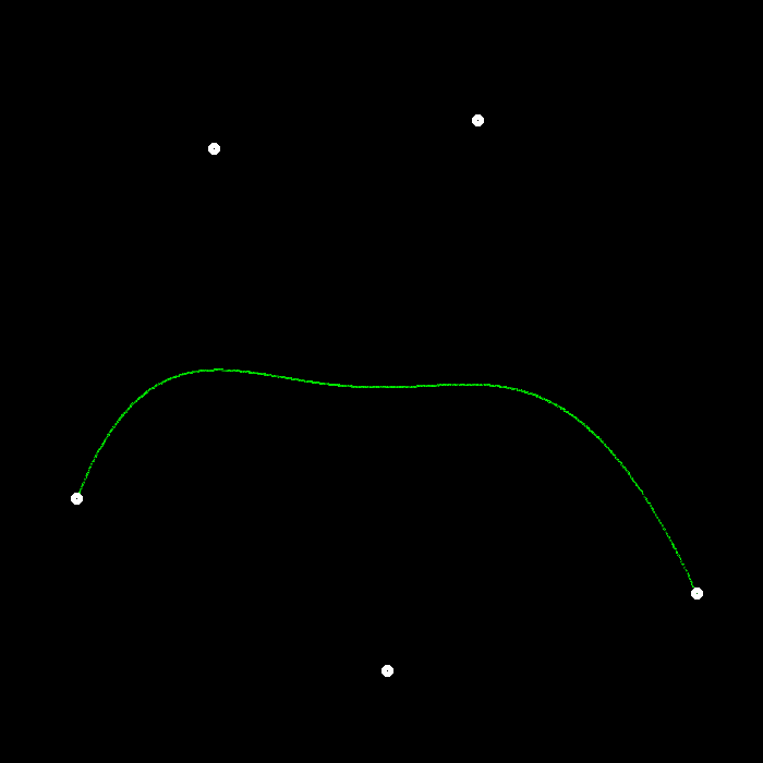
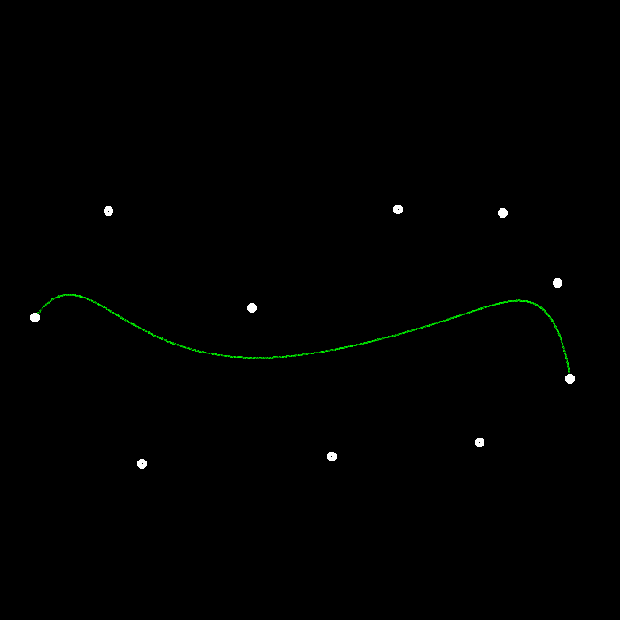
int point_num=4;//global variale voidmouse_handler(int event, int x, int y, int flags, void *userdata) { if (event == cv::EVENT_LBUTTONDOWN && control_points.size() < point_num)//这里修改为了point_num { std::cout << "Left button of the mouse is clicked - position (" << x << ", " << y << ")" << '\n'; control_points.emplace_back(x, y); } }
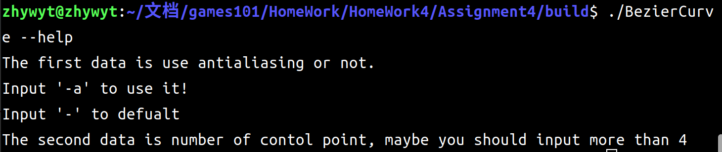
intmain(int argc,constchar*argv[]) { if(argc==2&&std::string(argv[1])=="--help"){ std::cout<<"The first data is use antialiasing or not.\nInput '-a' to use it!\nInput '-' to defualt\n" <<"The second data is number of contol point, maybe you should input more than 4"<<std::endl; return0; } cv::Mat window = cv::Mat(700, 700, CV_8UC3, cv::Scalar(0)); cv::cvtColor(window, window, cv::COLOR_BGR2RGB); cv::namedWindow("Bezier Curve", cv::WINDOW_AUTOSIZE); cv::setMouseCallback("Bezier Curve", mouse_handler, nullptr); bool use_anti =false; int key = -1; if(argc>=2&&std::string(argv[1])=="-a")use_anti=true; if(argc>=3&&std::stoi(argv[2])>4)point_num=std::stoi(argv[2]); while (key != 27) { for (auto &point : control_points) { cv::circle(window, point, 3, {255, 255, 255}, 3); } std::cout<<"point_num"<<control_points.size()<<std::endl;
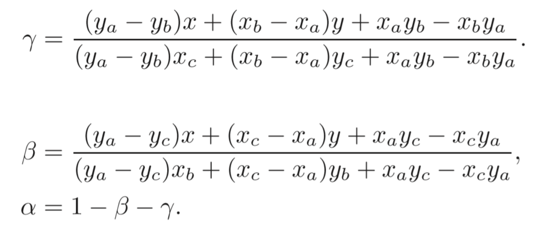
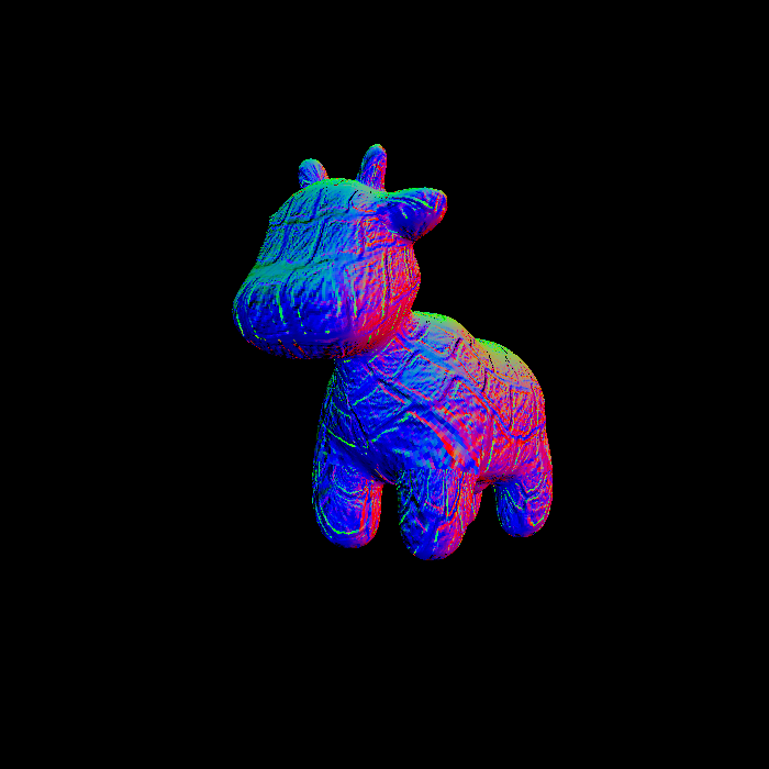
auto[alpha, beta, gamma] = computeBarycentric2D(i+0.5f, j+0.5f, t.v); auto interpolated_color=interpolate(alpha,beta,gamma,t.color[0],t.color[1],t.color[2],1); auto interpolated_normal=interpolate(alpha,beta,gamma,t.normal[0],t.normal[1],t.normal[2],1).normalized(); auto interpolated_shadingcoords=interpolate(alpha,beta,gamma,view_pos[0],view_pos[1],view_pos[2],1); //二维版本 auto interpolated_texcoords=interpolate(alpha,beta,gamma,t.tex_coords[0],t.tex_coords[1],t.tex_coords[2],1);
u = std::clamp(u, 0.0f, 1.0f); v = std::clamp(v, 0.0f, 1.0f);
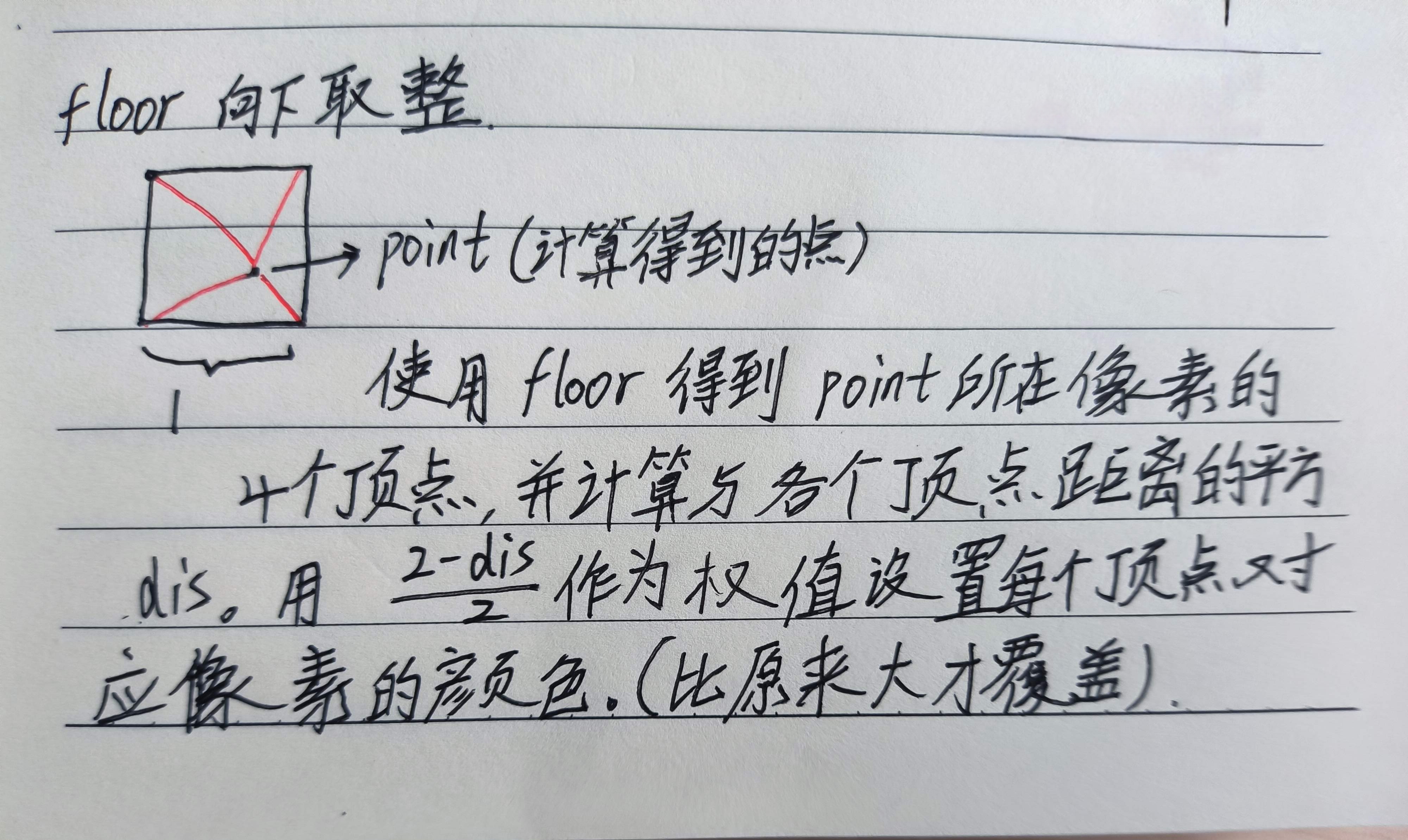
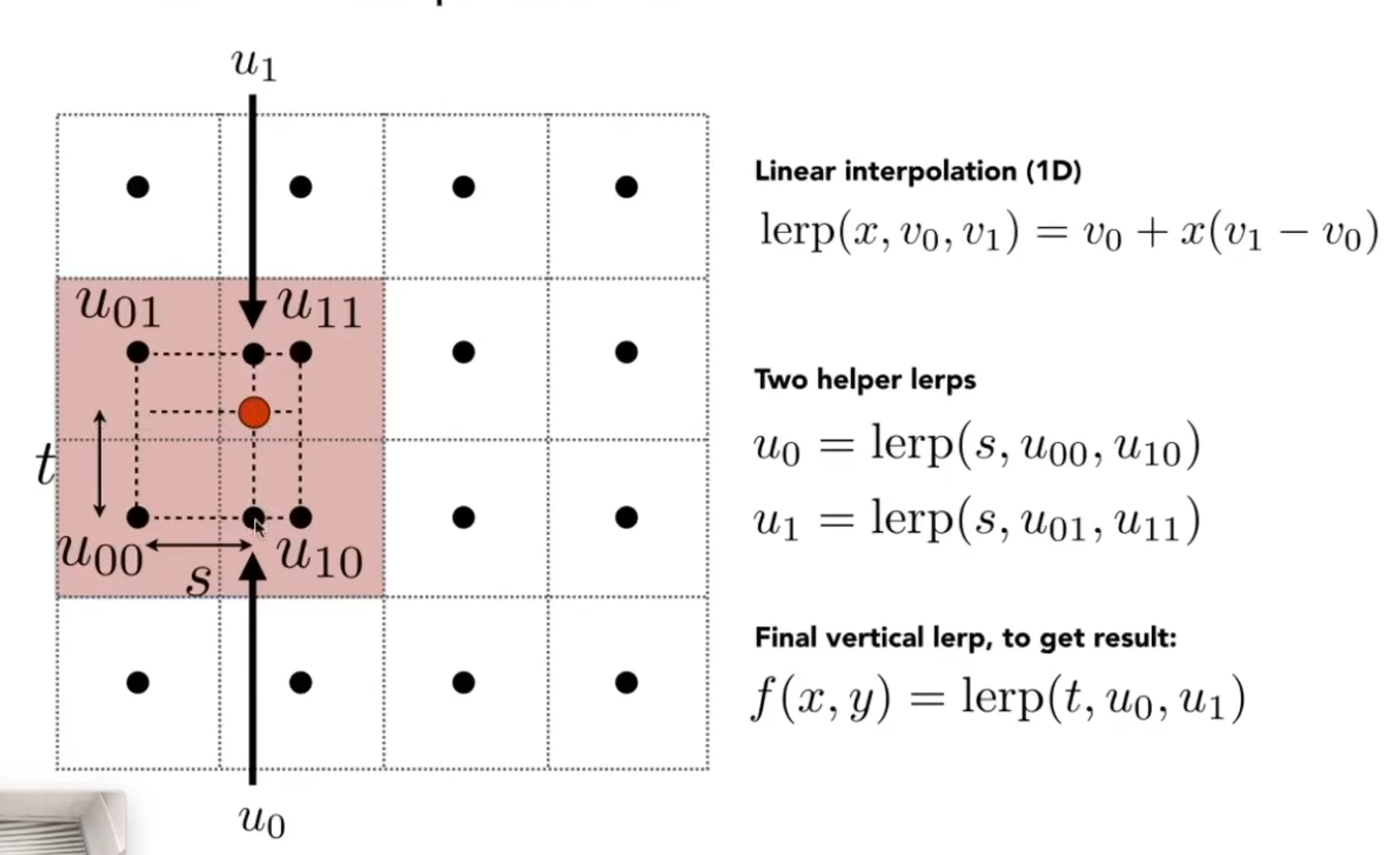
把比例转化为纹理坐标,并计算相邻的四个像素点
1 2 3 4 5 6
auto u_img = u * width; auto v_img = (1 - v) * height; float uMax=std::min((float)width,std::ceil(u_img)); float uMin=std::max(0.0f,std::floor(u_img)); float vMax=std::min((float)height,std::ceil(v_img)); float vMin=std::max(0.0f,std::floor(v_img));
其中
ceil()向上去整
floor()向下取整
记录四个点的颜色
1 2 3 4 5 6 7 8
//Up Left Point auto colorUL = image_data.at<cv::Vec3b>(vMax,uMin ); //Up Right Point auto colorUR = image_data.at<cv::Vec3b>(vMax, uMax); //Down Left Point auto colorDL = image_data.at<cv::Vec3b>(vMin, uMin); //Down Right Point auto colorDR = image_data.at<cv::Vec3b>(vMin, uMax);
单线性插值
1 2 3 4 5 6
float uLerpNum=(u_img-uMin)/(uMax-uMin); float vLerpNum=(v_img-vMin)/(vMax-vMin); //U Up Lerp auto colorUp_U_Lerp=uLerpNum*colorUL+(1-uLerpNum)*colorUR; //U Down Lerp auto colorDown_U_Lerp= uLerpNum*colorDL+(1-uLerpNum)*colorDR;
再进行一次插值
1
2
//V Lerp
auto color = vLerpNum*colorDown_U_Lerp+(1-vLerpNum)*colorUp_U_Lerp;
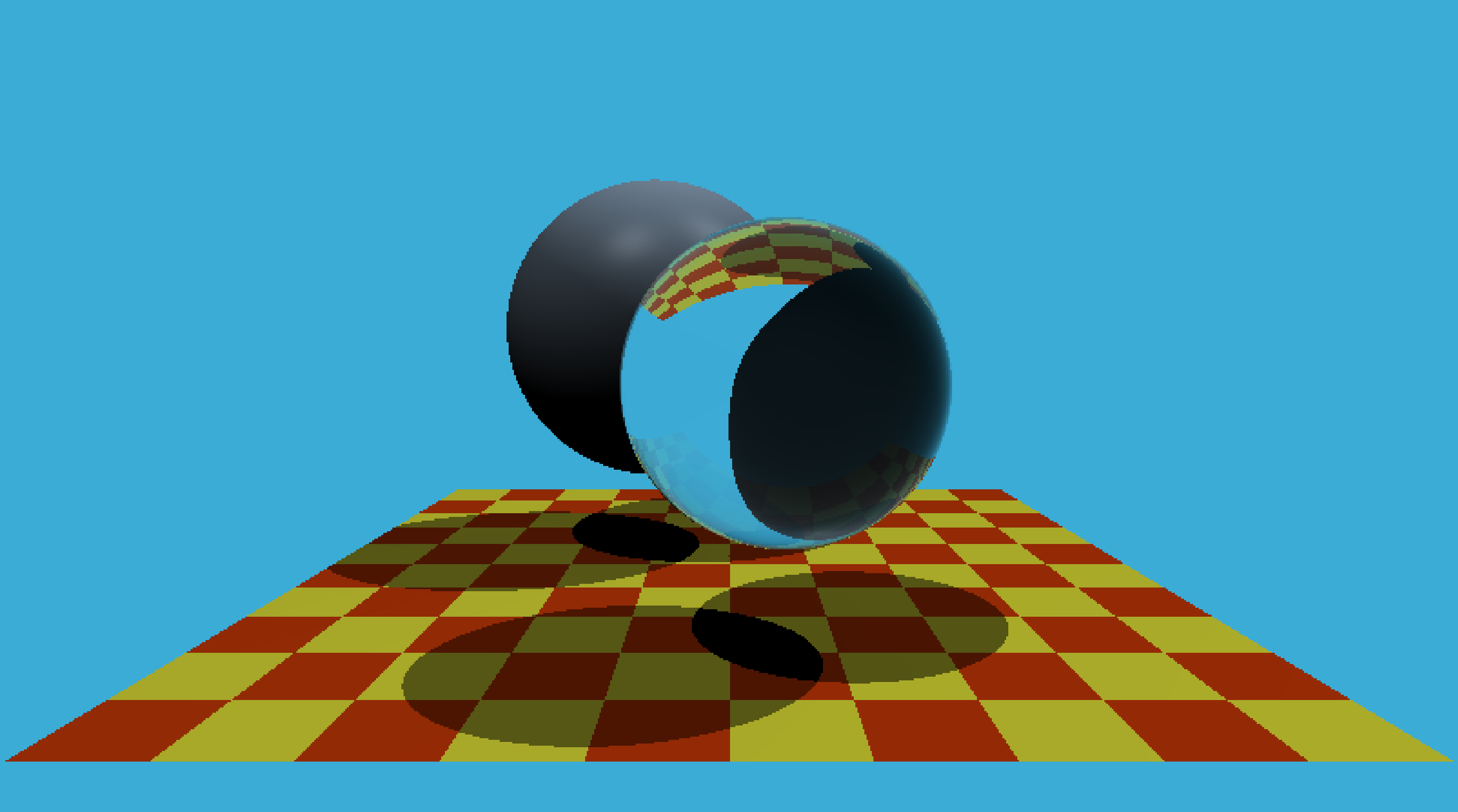
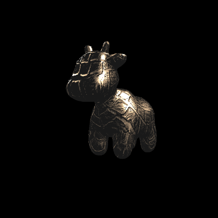
Eigen::Vector3f texture_fragment_shader(const fragment_shader_payload& payload) { Eigen::Vector3f return_color = {0, 0, 0}; if (payload.texture) { // TODO: Get the texture value at the texture coordinates of the current fragment //双线性插值 return_color=payload.texture->getColorBilinear(payload.tex_coords.x(),payload.tex_coords.y()); } Eigen::Vector3f texture_color; texture_color << return_color.x(), return_color.y(), return_color.z();
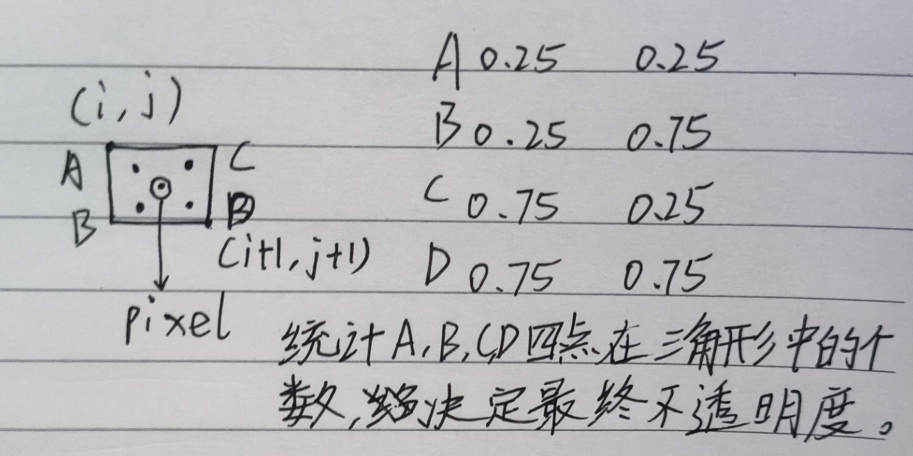
staticboolinsideTriangle(float x, float y, const Vector3f* _v) { // TODO : Implement this function to check if the point (x, y) is inside the triangle represented by _v[0], _v[1], _v[2] Vector3f P=Vector3f(x,y,_v[0].z()); //三边向量 Vector3f AC=_v[2]-_v[0]; Vector3f CB=_v[1]-_v[2]; Vector3f BA=_v[0]-_v[1]; //顶点与目标点向量 Vector3f AP=P-_v[0]; Vector3f BP=P-_v[1]; Vector3f CP=P-_v[2]; //if cross product in the same direction ,its inside the triangle if(AP.cross(AC).dot(BP.cross(BA))>0.0f&& BP.cross(BA).dot(CP.cross(CB))>0.0f&& CP.cross(CB).dot(AP.cross(AC))>0.0f) { returntrue; } returnfalse; }